
Analysis of ABS Harness Matching Design Scheme Applied to Automobile Wire Harness
2021-05-23
This paper mainly summarizes the matching design method of ABS harness, and draws the design criteria to be followed in the design of ABS harness for reference.
This article refers to the address: http://
When designing automotive wiring harnesses, the design principle should be to ensure the reliability of the work by connecting the shortest wires, the minimum number of wires, the most suitable wire cross-section and selecting the appropriate connectors and terminals for proper and reliable connection.
Wire type selection principle
1. Select according to the ambient temperature, for example, the ambient temperature around the engine is high, and there are many corrosive gases and liquids. Therefore, it is necessary to use high temperature, oil resistant, vibration and friction resistant wires; the wires on the trunk lid should maintain its elasticity at low temperatures, so use cold elastic wires to ensure normal operation; the wires on the automatic transmission must be resistant. High temperature, resistant to hydraulic oil, its temperature stability is good; due to the high temperature of the exhaust pipe of the car, it should be kept away from the exhaust pipe when laying the wire harness. If it is unavoidable, it is necessary to use wires larger than 200 °C, and adopt silicone rubber protective tube. Protection; wires used for brake shoe harnesses are required to be abrasion resistant, impact resistant (sand) and resistant to high and low temperature (temperature cycling) shocks.
2. Shielded wires should be used for sensors and weak signal sensors near the main sensor and strong interference sources to prevent electromagnetic interference.
3. Determine the wire standard. There are some differences in the conductor structure, nominal section, insulation material and thickness, performance requirements and maximum outer diameter of different standard wires. At present, China has begun to use the following automotive wire standards: ISO, SAE, DIN, JIS, VW, PSA, etc., the types of wires commonly used in automobiles include Japanese standard (AVSS, etc.), national standard (QVR), and German standard (FLRY).
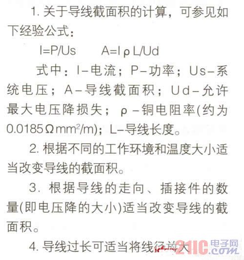
Principle of calculation and selection of wire cross-sectional area
The choice of wire cross-sectional area is mainly based on the voltage drop of the line, the change in ambient temperature and the mechanical strength of the wire. The voltage drop of the line = the voltage drop caused by the wire resistance + the voltage drop of the switch contact + the voltage drop of the terminal + the contact voltage drop of the terminal + the internal resistance drop of the power supply.
Wire color selection principle
The choice of wire color is based on user requirements and error-proof design. Generally, the grounding wire is black. See QC/T 414, "Colors of Low Voltage Wires for Automobiles", and consider error-proof design, such as the same connector in the wire harness. Do not use the same color wire of the same specification.
Connector selection principle
1. Ensure that the connecting parts are in good contact, the contact resistance is the lowest, and the reliability is improved. The connector of the double spring type pressing structure is preferred.
2. According to the cross-sectional area of the wire and the size of the passing current, the connector is reasonably selected. The currents that can be carried by different types of connectors are as follows: 1 series, about 10A; 2.2 or 3 series, about 20A; 4.8 series, about 30A; 6.3 series, about 45A; 7.8 or 9.5 series, about 60A.
3. According to the specific working environment, choose the corresponding anti-vibration, waterproof, dustproof and anti-pollution connectors, such as the environment where the temperature and humidity in the engine compartment are too large and there are many corrosive gases and liquids. Select the waterproof connector. .
4. If the same connector is used in the same harness, the color must be different for error-proof design.
5. Based on the overall coordination of the appearance of the car, the connector of the color matching the application environment should be preferred.
6. In order to reduce the type and number of connectors, it is preferred to use a hybrid type to make assembly easier.
7. For terminal connectors with higher safety systems, gold-plated parts should be preferred to ensure safety and reliability.
Based on the design principles of the relevant literature reviewed above, the design guidelines for ABS harness design are summarized as follows:
Design Guideline 1: Wiring Diagram Connection Requirements for System Solutions That Meet Different Functions
(1) The wiring diagram of ABS/ASR/EBL E version (4S/4M-S sensor; M solenoid valve)) is shown in Figure 1.
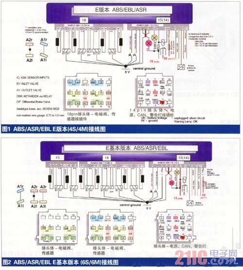
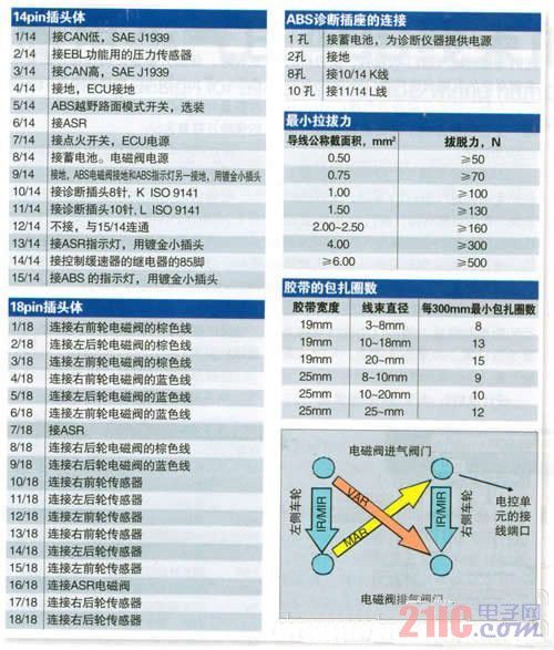
ABS diagnostic socket installation instructions: installation location:
Close to the electronic control unit or dashboard, easy to diagnose location.
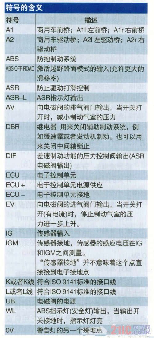
The green and yellow wires of all solenoid valves are grounded. The solenoid valve brown wire (EV) controls the air inlet and the blue wire (AV) controls the air outlet. The sensor leads are brown and black, but have no polarity.
(2) The ABS/ASR/EBLE basic version (6S/6M) wiring diagram is shown in Figure 2. The figure can be read according to the above explanation.
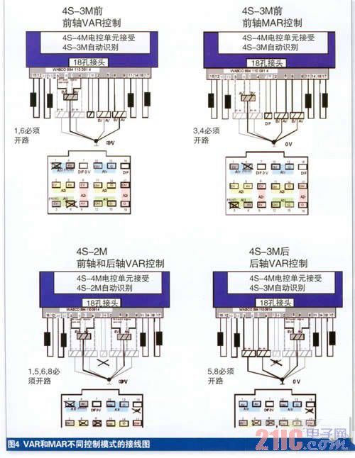
Design Guideline 2: Wiring Diagram Connection Requirements for System Solutions That Meet Different Control Modes
In order to reduce the product variant of the electronic control unit, for the 4S (S-Sensor) system solution, different control modes can be realized by different wiring methods, as shown in Figure 3, that is, the intake valve of the ABS solenoid valve through the controlled bridge. Different connection modes with the exhaust valve to obtain different control modes.
VAR control mode: solenoid valve exhaust valve AV wiring on the right side of the controlled bridge, solenoid valve intake valve EV wiring on the left side of the controlled bridge; solenoid valve intake valve on the right side of the controlled bridge The EV is an open circuit, and the solenoid valve outlet valve AV of the left side wheel of the controlled bridge is an open circuit.
MAR control mode: solenoid valve intake valve EV wiring on the right side of the controlled bridge, solenoid valve exhaust valve AV wiring on the left side of the controlled bridge; solenoid valve outlet valve AV on the right side of the controlled bridge For an open circuit, the solenoid valve intake valve EV of the left wheel of the controlled bridge is open.
The electronic control unit judges the control mode by detecting the load and the open circuit condition, and then automatically sets the system scheme parameters. If the connection is wrong, the invalid system scheme, the electronic control unit will report an error.
Design Guideline 3: Insurance Requirements for Power Cords
The power cord must be equipped with a chip insurance in accordance with ISO/DIS 8820. The capacity of the fuse is strictly selected according to the wiring diagram requirements, and it is not allowed to increase. The fuse power of the solenoid valve power supply is 15A (4M)/10A (3M), and the fuse size of the electronic control unit power supply is 5A.
Design Guideline 4: Requirements for Power and Ground Wires for Solenoid Valves
The power supply line and grounding wire of the solenoid valve must be less than 0.5V in any case (at a voltage of 24V, a solenoid valve current of 3.0A; at a voltage of 12V, a solenoid valve current of 4.4A;). 2.5mm2 wire and the grounding point is as close as possible to the electronic control unit;
Design Guideline 5: Requirements for Power and Grounding Wires for Electronic Control Units
When the grounding wire of the electronic control unit is at current 2A, the voltage drop should be less than 0.1V, and the cross-sectional area of the wire should be 1.5mm2. The cross-sectional area of the power and ground wires of the electronic control unit is recommended to be 2.0mm2.
Design Guideline 6: Requirements for Switching Wires
The voltage drop of the switch wire should be less than 0.5V at a current of 5mA.
Design Guideline 7: Requirements for other conductor cross-sectional areas
Recommended other wire cross-sectional area 0.75-1.5mm2
Design Guideline 8: Other Wire Voltage Drop Requirements
In any case, the wire voltage drop must be less than 0.5V.
Design Guideline 9: Grounding Point Requirements
Use the same grounding point for all grounding to ensure that the grounding point is well grounded.
In order to avoid electromagnetic interference, the grounding point of the ABS must be separate and not allowed to be shared with other powered devices.
Design Guideline 10: Requirements for Terminals for Indicators and Ground Wires
The terminals of the indicator light and the grounding wire must be gold-plated terminals to avoid the indicator light being constantly lit due to rust after prolonged use. In any case the voltage drop must be less than 0.5V.
Design Rule 11: Requirements for Relays
When the system is working, the retarder, engine brake and differential lock are not required to work, so relays should be installed for control.
Design Guideline 12: Sensor Wire Requirements
The design and installation of the conductor shall avoid electromagnetic interference. There shall be 20 knots or more per meter, and 50mm shall have a section; if there is no ordinary shell protection, each meter must be increased to 30 knots or more, and 30mm should have a section. .
Design Guideline 13: Requirements for Solenoid Wires
The diameter of the wire connecting the solenoid valve and the grounding wire must be selected so that the voltage drop can be less than 0.5V when the coil is energized at room temperature, the resistance is less than 0.28Q, and the recommended wire cross-sectional area is 1.5mm2.
Design Guideline 14: Requirements for Harness Design
• The wire harness material should be extended within 25mm from the tail of the molded case, except for a single wire.
• The label of the cable bundle should be indicated by the label and printed correctly, clearly, and firmly attached. The label should be affixed to approximately 50 mm from one end of the harness.
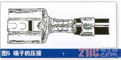
• Correct crimping is shown in Figure 5. For other terminal crimping quality requirements, please refer to the standard QC/T29106-1992/Appendix A.
• Minimum pull force test requirements
The connection between the terminal and the wire should be firm. The tensile force of the crimped wire harness should be tested at a rising speed of 200 mm/min. The minimum pulling force should be in accordance with the left table.
• Voltage drop test requirements
The detailed requirements for the voltage drop of the terminals refer to the standard QC/T29106-1992.
• Connecting nail requirements
• The crimping of the connecting nails can be performed by using a U-shaped terminal crimping method and ultrasonic welding, etc., and a special machine is required for crimping.
• The surface insulation of the crimped joint should be good and the conductor should not be crushed.
• The crimping point should be firm and should not be damaged or disengaged under the specified tension.
• Use a non-woven cloth tape for fixing the outside of the joint. In areas where waterproofing is required, the connecting nail must be protected by a heat-shrinkable tube. Heat shrinkable tube temperature resistance - 40 ° C - + 100 ° C.
Design Guideline 15: Requirements for Harness Protection
When the wire is passed through the hole, the rubber member is generally used for the transition to wear, waterproof, seal and the like. In addition, the harnessing design of the wire harness is also an important protective measure, which plays the role of abrasion resistance, flame retardant, anti-corrosion, anti-interference, noise reduction, and beautification of appearance. Generally, a dressing design scheme is formulated according to the working environment and space. The wiring harness associated with the engine has a harsh working environment, so it is completely wrapped with a bellows with high flame retardancy, water resistance and high mechanical strength. At the same time, the wiring harness working environment related to the engine compartment is also relatively poor. Most of the branches are also wrapped with a flame-retardant bellows, and some branches are wrapped with PVC pipes. The wire harness associated with the instrument has a small working space and a relatively good environment, and can be completely wrapped or entangled with tape. Since the chassis line has a large number of contact parts with the vehicle body, it is wrapped with a bellows to prevent the wire harness from being worn, and it is considered to leave enough the running margin for connecting the relatively moving parts.
•tape
The tape acts as a bundle, abrasion, insulation, flame retardant, noise reduction, marking, etc. in the wire bundle. The wiring harness tape is generally divided into three types: PVC tape, air-laid cloth tape and cloth tape. PVC tape has good wear resistance and flame retardancy; the temperature resistance is around 80 °C, the noise reduction is not good, and the price is relatively cheap. The flannel tape and the cloth tape material are PET. The banding property and the noise reduction of the flannel tape are the best, and the temperature resistance is about 105 °C; the abrasion resistance of the cloth tape is the best, and the temperature resistance is up to 150 °C. The common disadvantage of flannel tape and cloth tape is that it is not flame retardant and expensive.
Banding the wire harness with tape can be divided into fixed point wrapping, 1/2 folding wrapping, 1/3 folding wrapping, zero folding wrapping and gap wrapping (except single line). See the left table for the specific number of laps.
• Bellows
The end of the bellows should be more than 20mm from the end of the wire harness and fixed with PVC tape for more than 2 weeks.
The bellows has good wear resistance and is excellent in high temperature resistance, flame retardancy and heat resistance in the high temperature zone. The temperature of the bellows is between -40 and 150 °C. Its material is generally divided into polypropylene (PP) and polyamide (nylon) PA. PA material is superior to PP material in flame retardant and wear resistance; however, PP material is stronger than PA material in bending fatigue resistance.
• Polyvinyl chloride (PVC) casing
The end of the PVC sleeve should be more than 10mm from the end of the wire harness and fixed with PVC tape for more than 2 weeks.
PVC bushings are similar to bellows. The PVC pipe has good flexibility and bending resistance, and the PVC pipe is generally closed, so the PVC pipe is mainly used for the branch of the wire harness to make the wire smoothly transition. The heat resistance temperature of the PVC pipe is not high, generally less than 80%.
Design Guideline 16: Compliance with relevant standards
The following standards should be used when designing the harness:
(1) IS06722 road vehicles - 60V and 600V single conductors - dimensions, test methods and technical requirements
(2) QC 29106 automotive low-voltage wiring harness technical conditions
(3) QC 29005 automotive low-voltage wiring harness quality classification
(4) QC 29009 automotive wire joint technical conditions
(5) QC 29010 automotive low-voltage wire connector type, size and technical requirements
(6) QC 29012 Automotive Cylindrical Wire Socket Types, Dimensions and Technical Requirements
(7) GB9328 road vehicles with {眶 cable (wire)
(8) QC/T 417-418. Connector industry standard, color of QC/T 414 automotive low voltage wire
(9) QCJ/T420-2004. Automotive fuse standard
(10) QC/T 220-1996. Standard for automotive fusible wire
(11) DIN72551—6/1996. German standard wire standard
(12) JB/T 8139-1999, national standard wire standard.
Our wire harnesses are widely used for various parts of automobiles and truck , Like engine valve cover gasket/diesel gasket(DORMAN-FORD), headlamp(GROTE), Intelligent Anti-collision System(Mobileye), audio, rearview mirror, power seat, etc. Also the complete engine cable assembies for electric vehicle.
Related Products:ul wiring assembly,engine gasket cable,cable harness.
Automotive Wire Harness, Auto cable assemblies, OEM Automotive Wire Harness
Winnerlifting Industry & Trading Co., Ltd. http://www.oemwireharness.com